

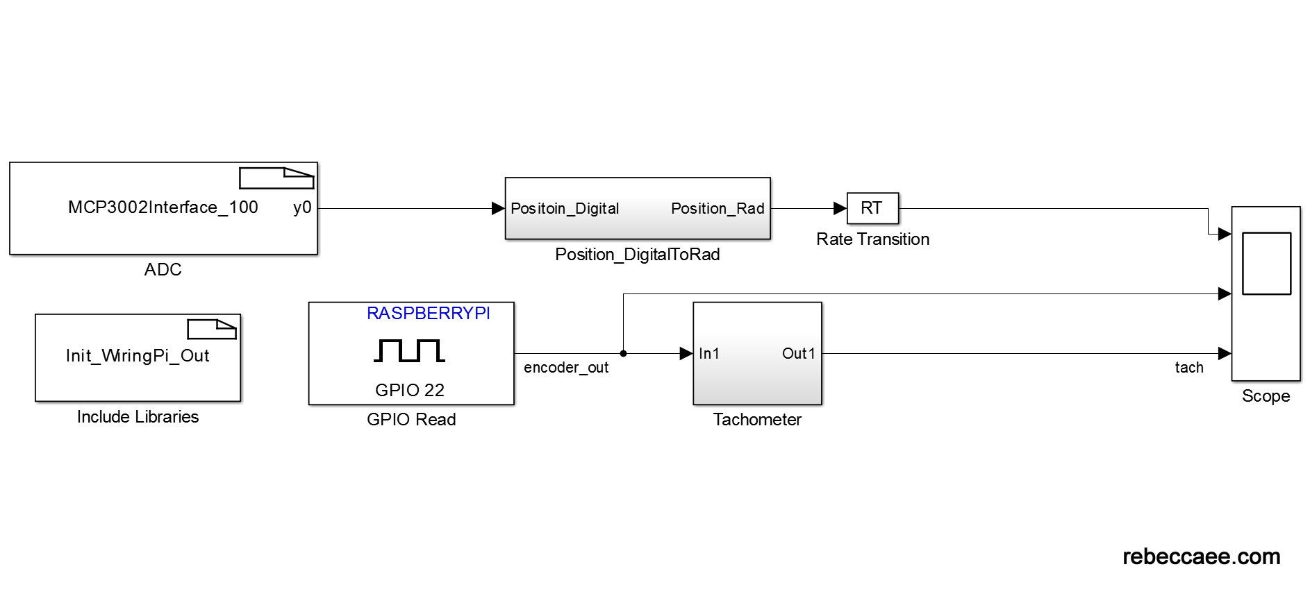
In order for the Raspberry Pi to read the motor's position from the potentiometer, the analog signal needs to be converted to a digital signal. I selected an MCP3002 analog-to-digital converter (ADC) for this purpose. The digital output from the MCP3002 can be read using the SPI or I2C protocols and the Raspberry Pi has built in drivers in the WiringPi libraries for both protocols. I used SPI in the GE320 kit because the driver already existed in WiringPi, which made the implementation very easy.
To implement this interface in Simulink, I used an S-Function driver. A model with a complete driver is available on MathWorks File Exchange. Or you can build your own using the following instructions.
On the Initialization tab, change the following parameters:
- Number of discrete states: 1
- Sample mode: Discrete
- Sample time value: 0.001 (this is the value I used, but it can be modified to fit your model)
On the Libraries tab, put the following code in the Includes box:
	#include <math.h>

	# ifndef MATLAB_MEX_FILE
	#include </home/pi/wiringPi/wiringPi/wiringPi.h>
	#include </home/pi/wiringPi/wiringPi/wiringPi.c>
	#include </home/pi/wiringPi/wiringPi/mcp3002.h>
	#include </home/pi/wiringPi/wiringPi/mcp3002.c>
	#include </home/pi/wiringPi/wiringPi/piHiPri.c>
	#include </home/pi/wiringPi/wiringPi/wiringPiSPI.c>

	#endif
In the Outputs tab, include the following code:
	if(xD[0] == 1)

	{
              #ifndef MATLAB_MEX_FILE
                   y0[0] = analogRead(100)/1023;
              #endif
         }
In the Discrete Update tab, include the following code:
	if(xD[0] != 1){
	     # ifndef MATLAB_MEX_FILE
                  wiringPiSetup() ;
                  mcp3002Setup(100, 0) ;
	     #endif
	     //done with initialization
             xD[0] = 1;
	}
Then click the Build button in the top right corner of the window.
If you select an MCP3004 or MCP3008 instead, the line to setup the MCP3002 can be changed to MCP3004.


